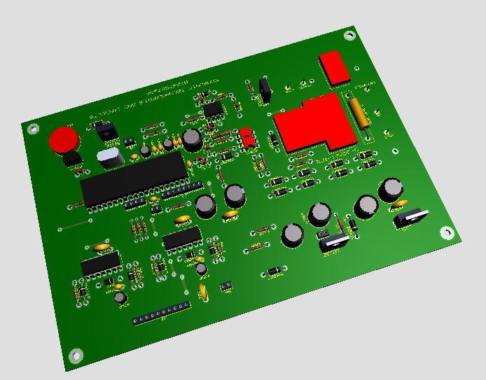
Samsonic Advancements and Counsels is the organization behind the inverter known as Sinus 2.1. By sticking to the parts’ marks, you can without much of a stretch collect the inverter. From 12 volts to 24 volts of supply voltage are viable with the board. An outside power supply is expected for 48v.
Arrangement of a 12V Inverter The accompanying things ought not to be incorporated while setting up a 12V inverter.
1k 2watt resistor, 15V Zener diode, TIP122 To finish the circuit, put jumper J1 and bind it on. IRF3205 is the most reasonable MOSFET incentive for this plan.
Arrangement of a 24V Inverter To set up a 24V inverter, jumper J1, and any remaining parts should be welded. Change out the 1N4007 for a gag. The stifle resistor shouldn’t surpass 22 ohms and 5 watts; a 10-ohm 5-watt gag is liked. Heat sinks for the LM7805 and TIP122 ought to be introduced accurately. IRF3207 or IRF4110 is the most reasonable MOSFET value for voltages more prominent than 3 KVA. Observe: For further developed execution, utilize an optocoupler with comparative properties or the FL817C. To abstain from wearing out, the 220k resistors ought to be evaluated at 2 watts. Except if generally noticed, any remaining resistors on the inverter card are 14 watts.
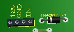
Arrangement of the 48V Inverter An outside SMPS (switch mode power supply) circuit is utilized to lessen the driver board’s 48V to 12V. No TIP122, 15V ZENER, 1K 2W resistor, or Jumper JP1 parts exist. With a jumper, substitute 1N4007 D1. Interface the SMPS as named in the image underneath. GND is the ground, IN is the info, and 12V is the result. The IF4110 MOSFET is the most ideal decision.
Notes on Binding While patching, focus on the places of significant parts like diodes, BD139 semiconductors, and BC547 semiconductors. The diodes should be situated properly. The semiconductors’ positions and direction are portrayed in the graph above, with BC547 bearing the names C, B, E, and BD139 E, C, and B.
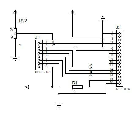
LCD Association The association between the inverter board and a 16 x 2 line LCD is portrayed in the chart above.
The inverter should be associated with the temperature sensor. The inverter won’t work in the event that the thermistor isn’t there. The thermistor has a 10k worth. The heatsink (positive battery terminal) holds the thermistor setup. Temperature control is on the fan.
Power On and Activity The H-span is utilized to work the inverter. Verify that the control signal terminals are appropriately associated.
The inverter is turned on by squeezing a button. Yet again the inverter resets itself when a shortcoming happens, and after the statement cycle, it is prepared for use. The inverter will be reset on the off chance that the shortcoming continues, and the client will be educated regarding the sort of issue.
Two significant tasks are involved.
Reinforcement Mode
Adjusting Mode
Reinforcement mode: in this mode, the inverter isn’t giving yield. This mode is placed by the inverter when it is switched off. The inverter starts charging 20 seconds after the utility power shows up. The inverter doesn’t give reinforcement power assuming that the mains power is lost until you press the press button to turn it on.
There is no misuse of force in reserve mode. The inverter is kept prepared to charge in any event when you are not there. It handles the charging of the inverter and switches off the inverter when there is a power outage.
The mode that Upsets: The inverter turns on and produces yield when the press button is squeezed once. The upset mode is this. Furthermore, it has a UPS highlight that guarantees that any associated machines don’t lose power in that frame of mind of a blackout.
CT Current Transformer/Associations Utilize any sort of current transformer, incorporating those with 5 amps. From the guide, An on the board toward point B, run a wire through the CT.
Interface the high-voltage sides of the transformers, TRANSFO_1 and TRANSFO_2, to each other. Interface Stage to the inverter’s result, and associate the board’s mains to mains.
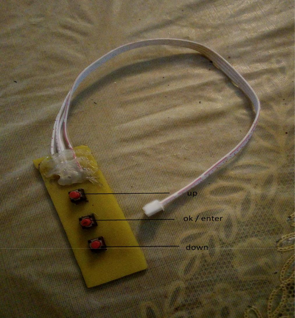
Arrangement BUTTON The buttons are utilized to set up the inverter and adjust it. The buttons are associated with the board’s buttons 4 pin attachment.
Whenever the inverter can enter adjustment mode. Be that as it may, entering the arrangement during altering is suggested. Prior to associating the charger, do this. The alignment must be done with a multimeter.
To enter arrangement mode, you hold down the okay/enter button.
You press the up button to change the worth of a boundary.
By squeezing the down button, a boundary worth can be diminished.
To save limit regard, you press the okay/enter button.
The battcuf ought to be set as the main boundary.
The battery cutoff boundary is BATTCUTF. To keep the battery from disintegrating, the inverter closes down at this voltage.
Set the battcutf on the 12v framework to 10v at least.
The base voltage for the 24v framework is 20v.
The base voltage for the 48v framework is 40v.
BATT2LOW
This is the battery voltage setting to start the low battery alert.
12v system set to 11v
24v structure set to 22v
48v structure set to 44v
BATTFULL
This is battery full settings. The not set in stone battery type was utilized. Prior to changing this setting, kindly consistently peruse the battery’s manual. This battery full is set to 13.8 volts of course. Prior to setting up the inverter interestingly, ensure you convey this arrangement.
12v system set to 13.8v
24v system set to 27.6v
48v system set to 55.2v
CHARGCUR
This limit is the charging current. Do whatever it takes not to enter this mode if you don’t have a fasten meter. Associate the cinch meter to the battery’s adverse terminal. The charging current can be expanded or diminished by squeezing the up or down buttons.
To save the ideal current, press the right/enter button. Contingent upon the transformer that is being utilized, the default charging current is 3.6 amps. Set the charging current to 8-10 amps for a 12-volt framework. The charging current on a 24-volt framework is 10 amps.
CHARGCAL This boundary is utilized to adjust the charger to the clip meter esteem. The charge can be expanded or diminished by squeezing the up or down buttons. To save, press the right/enter button.
O/P The result voltage is set by this boundary. This is used to change the voltage of the inverter to the beneficial voltage of 230v. Interface a multimeter to the inverter’s result. Ensure the air conditioner volts setting on the multimeter is set. The resulting voltage can be changed by utilizing the all-over buttons. To save, press the right button on the multimeter when the ideal voltage is reached.
O/P CAL This boundary is utilized to change the inverter’s LCD voltage so it matches the multimeter voltage.
I/P CAL is the boundary that is utilized to match the inverter’s LCD input voltage to the mains voltage. Partner the charge fitting to the mains, interface your multimeter, then, change the voltage until it arranges with the voltage on the multimeter. To save, press the right/enter button.
LOAD The reason for this boundary is load alignment. Interface the inverter to a heap with a known worth. You can set the greatest burden with the help of the ADC perusing shown on the LCD; observe it.
MAXIMUM_LOAD The most extreme burden is set by this boundary. Also, it tends to short out. Short out is 1.3 * most prominent weight, and the over-trouble trip is 1.2 * most outrageous weight. The most extreme burden is determined by duplicating the worth from the heap arrangement by an element.
I made this inverter