A sine wave inverter is an electronic gadget that converts direct current (DC) power into exchanging current (AC) power with a sine wave yield. This instructional exercise will tell you the best way to fabricate a basic half-bridge sine wave inverter utilizing a PIC12F683 microcontroller and an IR2103 MOSFET driver.
The half-bridge inverter comprises two switches, each associated with one terminal of the heap. On the other hand, the switches are turned here and there to deliver an air conditioner waveform. The PIC12F683 microcontroller is utilized to produce the control signals for the MOSFET driver, which thusly drives the MOSFET switches.
Here are the parts needed to build the inverter:
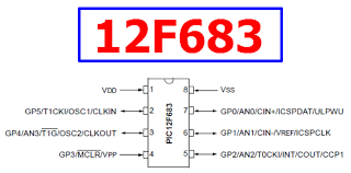
PIC12F683 microcontroller
IR2103 MOSFET driver
Two MOSFETs (for example, IRF3205)
A 12V battery or power supply
A DC move-forward converter (to create the necessary voltage for the microcontroller)
A 6V to 220V transformer
A Ceramic Filter Capacitor 3.3uf or 335J (to smooth the resulting waveform)
Here are the steps toward constructing the inverter:
Stage 1:
Program the PIC12F683 microcontroller to produce a sine wave yield. You can utilize a query table or a numerical recipe to create the sine wave. The result ought to be a PWM signal with a recurrence of around 50Hz.
Stage 2:
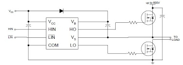
Interface the PIC12F683 microcontroller with the IR2103 MOSFET driver. The IR2103 MOSFET driver requires two information signals: the high-side MOSFET and the low-side MOSFET. Interface the PWM result of the microcontroller to the two contributions of the MOSFET driver.
Stage 3:
Associate the MOSFETs with the MOSFET driver. The MOSFETs ought to be associated in a half-bridge design, with the channel of one MOSFET associated with the heap and the source associated with the ground. The wellspring of the other MOSFET should be associated with the heap, and the channel should be associated with the 12V battery or power supply.
Stage 4:
Associate the DC move-forward converter to the 12V battery or power supply. The result of the move-forward converter ought to be associated with the VDD pin of the microcontroller.
Stage 5:
Associate the 12V to 220V transformer to the heap. The transformer ought to be evaluated for the resulting power of the inverter. The result of the transformer ought to be associated with a channel circuit to smooth the resulting waveform.
Circuit Diagram Below

Stage 6:
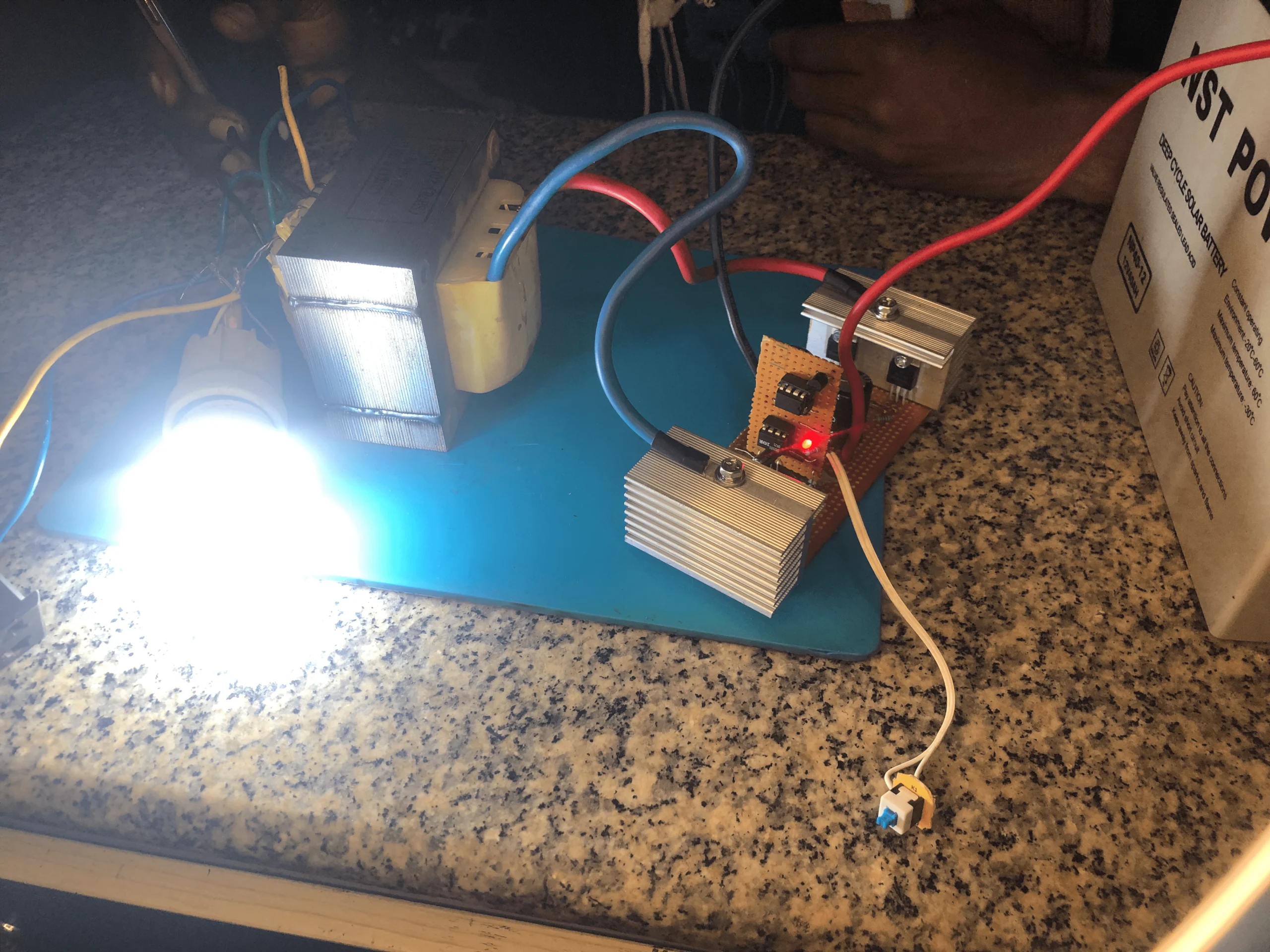
Test the inverter by interfacing a heap to the result. The heap should be a resistive burden like a light or a warmer. Notice the resulting waveform utilizing an oscilloscope and change the PWM recurrence and obligation cycle to accomplish a spotless sine wave yield.
Building a half-bridge sine wave inverter utilizing a PIC12F683 microcontroller and an IR2103 MOSFET driver is an extraordinary method for discovering power hardware and microcontroller programming. You can construct your own AC power supply for particular fundamental parts and a tad of programming for different applications.
VIDEO BELOW
You can download the project files, hex code, and schematic in the link below