Reason of the use of noise intensity meter
Noise pollution is tends to many non-communicable diseases and. Safe level of noise is considered up to 30 dB. Here is a interesting circuit by dreamlover technology, “Noise Meter” used to measure the level of noise indicting by LED and in addition it give warning when noise crosses the safe level of 30 dB by beeping sound.
Circuit description of Noise meter
The entire circuit of noise meter has been designed and fabricated using sound intensity sensor and display unit. Here condenser microphone is used as sensor of noise meter with operational amplifier (IC2) and corresponding passive components. The inverting and non-inverting input is given to operational amplifier IC (IC2) from pin 2 and pin 3 respectively. Where output from pin 6 of IC2 is connected to the inverting input for negative feedback through resistor R5.
Normally, sound intensity up to 30 dB is pleasant. Above 80 dB, it becomes annoying. And if it goes beyond 100 dB, it may affect your psychomotor performance, detracting your attention and causing stress. Noise pollution may also affect your hearing ability
project circuit diagram below
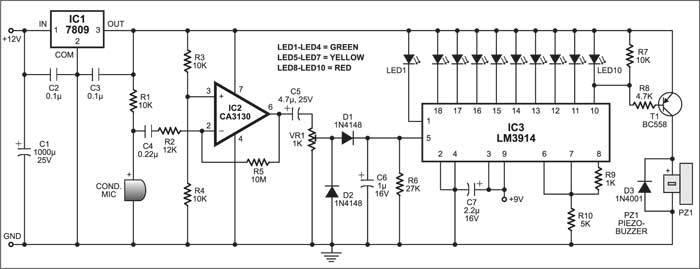
The controlling sound ac signal from potentiometer VR1 is first rectified by diode (D1 and D2) and maintains it at the output level of IC2.
The display unit is designed around monolithic IC LM3914 (IC3). It drives ten LEDs by sensing analog voltage. Each LED is connected to output of IC3 represents the sound level of 3 dB in descending order from 18 to 10. The glowing all ten LEDs indicate sound intensity is 30dB.
The PNP transistor get base bias when output at pin 10 of IC3 goes low to drive the piezo buzzer in order to give sound.