Introduction:
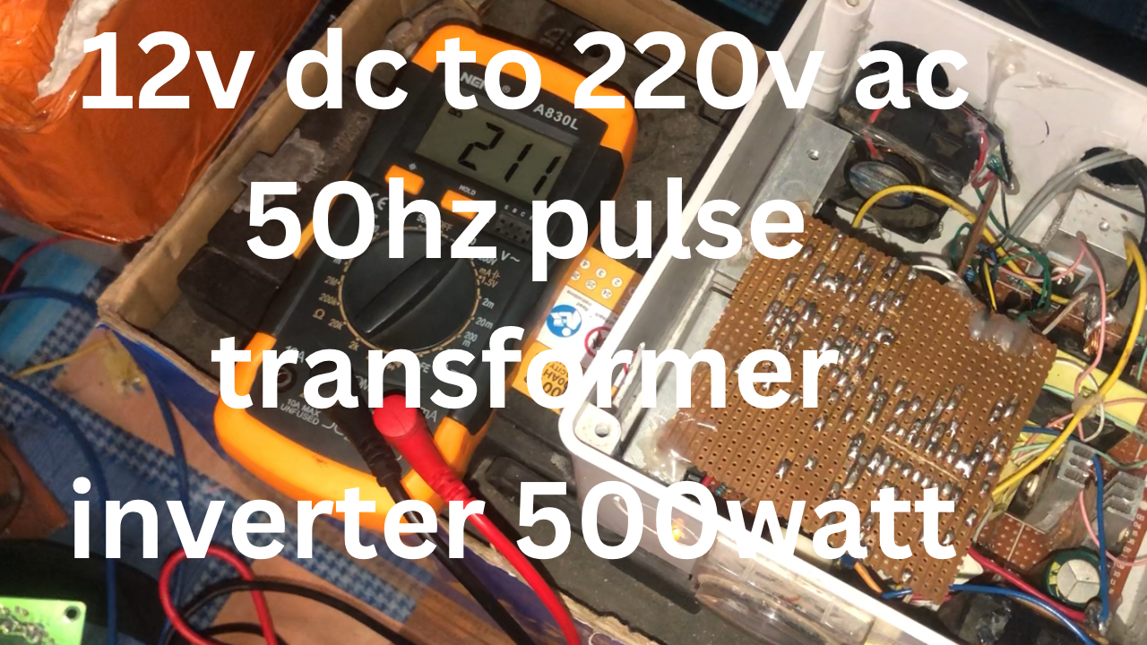
In the ever-evolving world of electronics, hobbyists often find joy in pushing the boundaries of what’s possible. One fascinating project that combines skill, innovation, and efficiency is the creation of a high-frequency inverter using the SG3525 IC. This versatile integrated circuit forms the heart of a design that transforms a humble 12V DC input into a robust 220V AC output at 50Hz. Let’s delve into the intricacies of this project, exploring the components and design choices that make it a powerful tool for electronics enthusiasts.
The SG3525 Oscillators:
There are 2 oscillators in the project the first is for the push-pull boost converter and the second is for the H-bridge circuit
The Push-pull boost oscillator
At the core of this high-frequency inverter lies the SG3525, a pulse width modulation (PWM) controller. Operating at an impressive 60kHz, the SG3525 generates precise and controlled pulses, providing the foundation for efficient power conversion. This oscillator sets the rhythm for the entire system, orchestrating the dance of electrons through the subsequent stages of the inverter.
Push-Pull Configuration with IRF3808 MOSFETs:
The heart of any inverter is its power stage, and here, a push-pull configuration takes center stage. Four IRF3808 MOSFETs are employed to create a dynamic push-pull arrangement, ensuring a balanced and efficient power transfer. These MOSFETs act as electronic switches, rapidly turning on and off in response to the SG3525 oscillator, facilitating the conversion of DC to high-frequency AC.
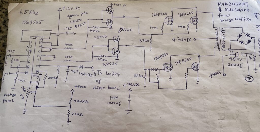
Chopped Transformer and Bridge Rectifier:
A key element in this inverter design is the center-tapped chopped transformer. This specialized transformer efficiently steps up the voltage to the desired 220V AC level. Following this high-frequency transformation, a bridge rectifier rectifies the AC waveform back into a stable DC voltage. This dual-stage process ensures a consistent and reliable power output.
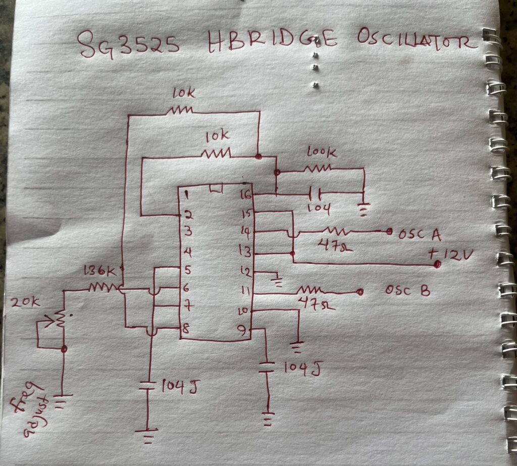
The Hbridge oscillator circuit
H-Bridge Circuit for 50Hz Operation:
To convert the high-frequency AC output to the standard 50Hz, an H-bridge circuit takes the stage. Utilizing IRFP460 MOSFETs, the H-bridge configuration intelligently switches the output to mimic the standard household power frequency. The SG3525 once again plays a crucial role in controlling this H-bridge, synchronizing the operation for seamless performance.
Drive Mechanism: Optocouplers, Transistors, and More:
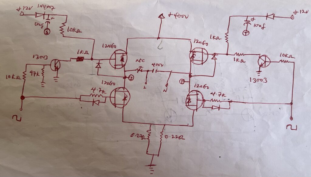
Efficiently driving the upper MOSFETs of the H-bridge is achieved through optocouplers, specifically the PC817 model. This ensures isolation between the control circuit and the high-power stage. On the lower side, S8050 transistors come into play, providing the necessary drive for the IRFP460 MOSFETs. This meticulous design optimizes performance and reliability.
Auto Voltage Feedback Control Circuit:
An inverter’s efficiency is significantly enhanced by incorporating an auto voltage feedback control circuit. This feature allows the inverter to adapt to varying load conditions and maintain a stable output voltage. The intelligence behind this control circuit is a testament to the sophistication achievable in DIY electronics projects.
video here
Conclusion:
Building a high-frequency inverter from scratch, especially one with specific design choices like the SG3525 oscillator and a push-pull configuration, is a rewarding endeavor for electronics hobbyists. This project showcases the synergy between various components and the careful integration of technologies to achieve a seamless and efficient power conversion process. As technology continues to advance, the possibilities for such projects only expand, offering enthusiasts new horizons to explore in the realm of electronics.