The Intro
This project is a simple smps 12v to 19v boost converter circuit or project for charging laptops and other devices that need higher voltage than 12v.
SMPS
SMPS, or Switched-Mode Power Supplies, are very important in electronics because they provide controlled power efficiently. We look into the details of making a 12V to 19V boost converter with the SG3525 PWM controller and IRFZ44 MOSFETs in this blog post. The SG3525, a PWM controller, is at the heart of this design. It provides precise control for the best power source performance.
SG3525 is a PWM controller.
The SG3525 PWM processor is what makes our boost converter work. This flexible IC creates accurate PWM signals with the help of an outside feedback loop, which lets the output voltage be controlled very precisely. Because it is so adaptable, it is often chosen for different power source setups, especially when raising the voltage from 12V to 19V.
MOSFETs as Parts of Switching
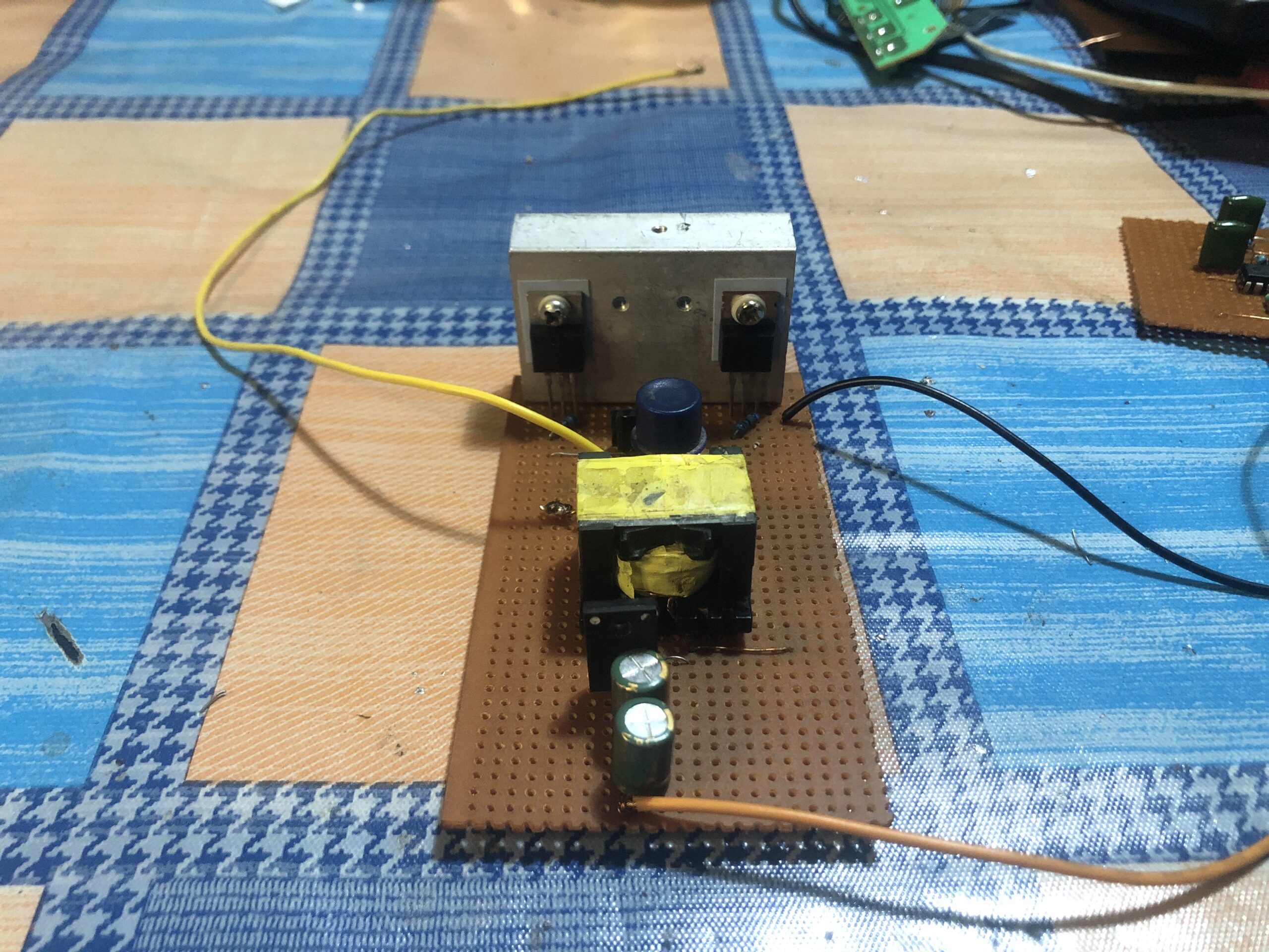
To convert power efficiently, two IRFZ44 MOSFETs are used as switching elements in a push-pull arrangement. These MOSFETs handle high-frequency switching well, reducing power loss and increasing total efficiency.
Time and Control of the Gate
For ideal switching, the IRFZ44 MOSFETs’ gate control must work well. Using 6.8kΩ gate-to-source resistors makes it easier to control the switching between on and off states. The 47Ω resistors that connect the SG3525’s PWM input to the MOSFET gates also fine-tune the switching characteristics, which makes the converter work better overall.
Changing the pulse and rectification
The SG3525 PWM signal is kept separate from the power circuit by a push-pull pulse transformer. This makes it safer and more reliable. After the transformer, a Schottky diode and a 25V 470µF capacitor work together to smooth out and correct the pulsed output. This makes a stable 19V DC output that can power electronics safely.
Feedback Loop and Controlling the Voltage
It is very important to keep the output voltage fixed. A feedback loop is set up in our 12V to 19V boost converter by connecting a 10kΩ resistor to the output and a 10kΩ potentiometer. The SG3525 can change the PWM duty cycle dynamically based on the difference between the desired output voltage and the real output voltage thanks to this loop.
The 10kΩ potentiometer can be used to change the input to the SG3525, which lets you fine-tune the output voltage. The feedback loop changes the PWM signal when the output voltage isn’t exactly what was set. This keeps the 19V output stable and correct.
Component Used
Resistors
R1, R2, R4= 47ohms
R3= 220Kohms
R7, R8= 6.8Kohms
R5,R9= 10Kohms
POTENTIOMETER R6=10Kohms
Mosfets
Q1, Q2= IRFZ44
IC (integrated circuit)
U1 = SG3525
C1,C2,C7= 104J
C3= 102J
C4= 25V 470UF
Transformer
Pulse transformer 4*2 turns which means center tap primary, 6 turns Secondary
SWITCH
power switch to turn on and off the circuit
Video here
Conclusion
the SG3525 12V to 19V boost converter with IRFZ44 MOSFETs is a reliable and effective way to give power. The SG3525 PWM controller, IRFZ44 MOSFETs, pulse transformer, and feedback loop were carefully chosen as parts that help achieve high performance, dependability, and stability.
This boost converter, which changes 12V to 19V, shows how advanced PWM control, high-frequency switching, and good feedback systems can work together in harmony. We can see that these parts work well together to make precise and effective power conversions for many electronic gadgets.