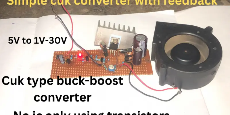
Today I am reviewing my simple DC to DC Cuk converter project (low-side drive type of DC to DC buck-boost converter)
Firstly What is a Cuk converter
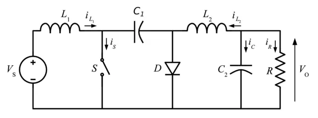
A Cuk converter is a type of converter that comprises both a buck converter and a boost converter which has only one switching device (Transistor, Mosfet, or IGBT), and the output current and energy are coupled with an electrolytic capacitor
These are the characteristics of a dc to dc cuk converter
- There is a reverse in the polarity of the output voltage side of the converter also similar to a buck-boost converter, in addition, to its polarity.
- It is a type of converter that has almost the same characteristics as the Buck-Boost Converter
Applications of Cuk Converter
- cuk converters are used as a voltage regulator
- They are used in hybrid solar-wind systems to make the output voltage constant
Advantages of Cuk Converter
- It has a low ripple current
- The efficiency is high up to 90%
- Switches(Mosfets, Transistor, or IGBT) are easy to drive because they are on a low-side drive
- Good EMI-EMI result which means the 2 inductors can share a core
Cuk Converter Topology Image below
Introducing my Simple Cuk Converter project.
Discuss the motivation for the project.
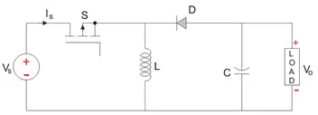
What motivated me to actually build a Cuk converter is that I have tried the normal buck-boost converter severally and I realized that their switch drive is very complex because the switching is a high side drive so I tried a Cuk converter out and it actually works.
Check this Buck-Boost image below to actually understand what I meant
Component list of the Cuk Converter Project
- Resistors
- Variable resistor 20k ohms
- resistor 470 ohms 4pcs
- resistor 20k ohms 2pcs
- resistor 2k ohms 1pc
- resistor 3k ohms 1pc
- Transistors
- Mosfet IRLB4132 1pcs
- S8050 3pcs
- Diodes
- 1n4007 1pc
- 5A Schottky diode 1pc
- Zener diode 3v 1pc
- Capacitors
- 102 J capacitor 2pcs
- 50v 10uf 1pc
- 50v 1000uf 1pc
- 35v 470uf
- Inductor
- 2 ferrite E core wound with 0.2mm copper wire 20 turns each on core
Note the operating frequency of the circuit oscillator is 60khz
Here is the circuit diagram drawn below


Watch this video of me testing the project
Evaluate the results of the project.
With my testing and use of this project, my evaluation of my project is up to 85%
discussion of future directions for the Simple Cuk Converter.
I think in the meantime I will try to increase the workability and efficiency of this project the functionality of this project is it ok for use but I will just try to improve the project