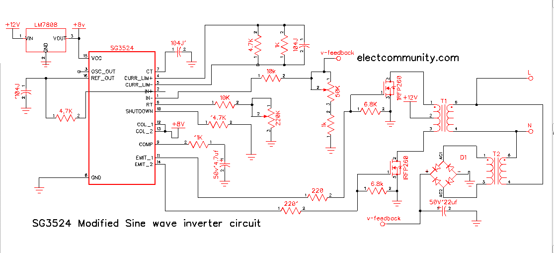
A push-pull inverter is a type of power inverter that generates alternating current (AC) voltage from direct current (DC). The push-pull inverter configuration consists of two switching transistors connected to a center-tapped transformer. The SG3524 Integrated Circuit (IC) is used in this configuration to control the timing of the switching transistors and produce a clean sine wave output.
The push-pull inverter has distinct advantages over other types of inverters. It can produce a high-quality sine wave output, capable of powering sensitive electronic devices while also being highly efficient in conversion. Here is a step-by-step explanation of how the push-pull inverter with the SG3524 IC works.
Step 1: DC Input
The push-pull inverter takes direct current (DC) input, which can be derived from a DC power supply or battery. The DC voltage is typically in the range of 12V to 48V, depending on the application.
Step 2: SG3524 IC
The SG3524 IC is a pulse width modulation (PWM) controller that regulates the switching transistors’ timing. The IC generates square wave pulses, at a frequency of some kHz, in response to the input DC voltage. The signal is used to drive the switching transistors.
Step 3: The Two Transistors
This push-pull inverter uses two switching transistors, typically NPN and PNP, at pin 14 and 11 respectively as Totem poles, so that the sg3524 will work efficiently without any interruption they are also Totem poles are good Mosfet drivers and so its signal is then passed to the Mosfets gate which will feed the center-tapped transformer. They operate in a complementary fashion, with one transistor switching on while the other is switching off. This alternating operation tends to produce a cleaner sine wave output compared to single-transistor designs.
Step 4: Center Tapped-Transformer
The transformer used in a push-pull inverter is center-tapped to help balance the loads on the two transistor ends. The two switching transistors alternately connect the transformer to the positive and negative sides of the DC input. As such, at any given time, half of the transformer windings are seeing the positive DC voltage, while the other half see the negative voltage.
Step 5: Switching Transistor Operations
The switching transistors are driven by the SG3524 IC, so they turn on and off alternately at different times. When one of the transistors (e.g., the NPN) is switched on, it allows the current to flow from the positive DC voltage through the transformer windings and out to the output load. During this time, the other transistor (e.g., PNP) is switched off, and it becomes an open circuit.
Step 6: The Output Load
The AC output voltage from the push-pull inverter is connected to the output load. Devices like power tools, appliances, or home electronics can be powered using the output of the push-pull inverter.
In the push-pull inverter, the output voltage is symmetrical, with same-amplitude positive and negative alternations of the sine wave. When the other switching transistor (PNP) is turned on and the positive transistor (NPN) is turned off, the AC voltage polarity reverses. This switching operation of the two transistors at different times alternates the DC input polarity to produce a clean and efficient AC output signal.

Step7: Auto Voltage Feedback Circuit
The SG3524 is a pwm ic and also has the capability to change its pwm duty cycle and switch to regulate the output voltage, So pin 1 of the Sg3524 is the Voltage feedback control pin of the pwm, so the ic sense the output voltage of the inverter by a feedback loop or auxiliary winding voltage from the transformer
Cons of Sg3524
- It works best at low frequencies and for the high-frequency circuits, you need sg3525
- You will need another circuitry for battery monitoring and also an auto changeover circuit to make the inverter charges its battery when ac mains presence
In conclusion, a push-pull inverter with SG3524 IC is a useful tool for powering sensitive electronic devices that require high-quality, stable AC voltage. The SG3524 IC controls the timing of the switching transistors to produce a clean and efficient AC output signal. The push-pull inverter can be designed for a wide range of applications and voltages, making it a versatile and cost-effective solution for many industries.
>>>Click here to download the schematic diagram<<<