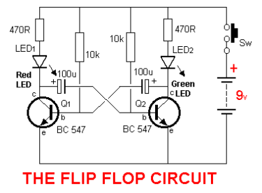
A flip-flop LED light with two NPN transistors either S8050 or bc547 transistors and two LEDs is an electronic device that can alternate the lighting of two LEDs in sequence. The circuit is easy to build, affordable, and provides a switching mechanism to display alternating LED patterns. Here are the steps involved in building a simple flip-flop LED light with two S8050 or bc547 transistors and two LEDs.
Components needed for this project:
– Two S8050 or bc547 NPN Transistors
-2pcs of 10k resistor
– Two LEDs (any color)
– 2pcs of 470Ω resistor
– 2pcs Capacitor (100μF)
– PCB Board, vero of perf board
– Soldering Iron and Solder
-a mini switch
– Power source (6V or 9V battery)
Steps to assemble the components:
1. Begin by assembling the required components for the circuit.
2. draw the circuit diagram for the flip-flop LED light, making sure all components and connections are represented properly.
3. Place the first transistor (bc547 or S8050)and 330Ω resistor on one side of the PCB board.
4. Connect the negative legs of the first and second LED to the 470Ω resistor.
5. Connect the positive leg of the first LED to the collector of the first transistor.
6. Connect the anode pin (positive leg) of the second LED to the collector pin of the second transistor.
7. Connect the emitter pin of the first transistor to the positive(+) terminal or pole of the power source or battery.
8. Place the second transistor and capacitors on the other side of the PCB board.
9. Connect the other end of the 470Ω resistor to the negative (-) pin of the second LED bulb.
10. Connect the base of the second transistor to the positive leg of the first LED through the 100μF capacitor.
11. Connect the base of the first transistor to the positive leg of the second LED through the 100μF capacitor.
12. Connect the emitter pin or leg of the second transistor to the negative terminal or ground pin or pole of the power source or battery.
13. Finally, power the flip-flop LED light using a 6V or 9V battery.
14. Observe how the LEDs alternate in lighting up in sequence.
Conclusion:
This project is a basic and simple project, it is more liked by electronics hobbyists who are beginners in the electronics field
building a flip-flop LED light with two transistors and two LEDs is even more enjoyable than assembling a single one. Careful observation of component rating and polarities, together with proper soldering techniques, will enable the building of sturdy electronics. A flip-flop circuit is created by connecting the transistors in a way that allows one LED to light up while the other is off or dimly lit. The 470Ω resistor limits the current to the LEDs to prevent them from burning out. The capacitors (2 pc of 100μF) allow the LEDs to turn on and off by the transistor. The transistors allow the current that passes through the base to amplify to the collector, which drives the LED ON and OFF. The flip-flop LED light with two transistors and two LEDs can be used for decoration, entertainment, or educational purposes. It can also act as a control system used for indicating status updates, alarms, or schedules.