A push-pull inverter is a sort of electronic circuit that changes over DC (Direct Current) power into AC (Rotating Current) power. The circuit utilizes two transistors, regularly a BJT (Bipolar Intersection Transistor) and a MOSFET (Metal Oxide Semiconductor Field Impact Transistor), to create the air conditioner yield. In this article, we will examine how to make a straightforward push-pull inverter utilizing BJT and MOSFET.
Components Required:
NPN BJT transistor (e.g., S8050)
N-channel MOSFET transistor (e.g., IRFP260)
resistors (e.g., 100kohms, 1kohms,6.8kohms, 220 ohms)
center-tapped transformer (e.g., 12 V – 0 – 12 V, 2A)
One 12V DC power source
Breadboard and jumper wires
Circuit Diagram:
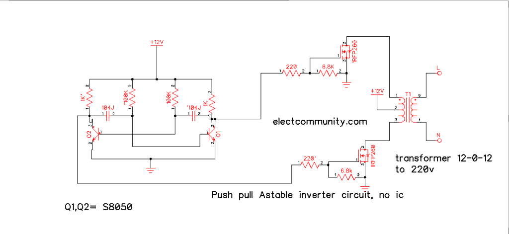
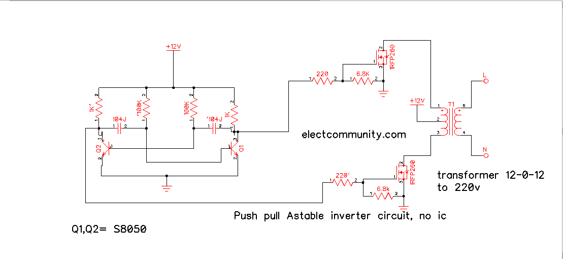
Coming up next is the circuit diagram for the push-pull inverter utilizing BJT and MOSFET.
How it functions:
The circuit utilizes two transistors, a BJT and a MOSFET, to produce the air conditioner yield. The two transistors are associated in a push-pull setup, and that implies that they on the other hand switch on and off to deliver the air conditioner signal.

The foundation of the NPN transistor is associated with the positive terminal of the DC power source through resistor R1. The producer of the NPN transistor is associated with the foundation of the N-channel MOSFET, which is likewise associated with the positive terminal of the DC power source through the transformer. The wellspring of the MOSFET is associated with the middle tap of the transformer, and the channel is associated with the adverse terminal of the DC power source through resistor R2.
At the point when the NPN transistor is turned on, it permits current to course through the essential twisting of the transformer. This current makes an attractive field that prompts a voltage in the optional twisting of the transformer, which is associated with the heap. Simultaneously, the MOSFET is switched off, keeping current from moving through the transformer.
At the point when the NPN transistor is switched off, the attractive field breakdowns, prompting a voltage the other way in the optional twisting of the transformer. This voltage is likewise associated with the heap. Simultaneously, the MOSFET is turned on, permitting current to move through the essential twisting of the transformer.
This cycle rehashes, with the NPN transistor and the MOSFET on the other hand turning on and off to create the air conditioner yield.
Conclusion:
In this article, we have explain how to make a simple push-pull inverter using BJT and MOSFET. The circuit is simple to construct and gives a basic knowledge of how push-pull inverters work.
