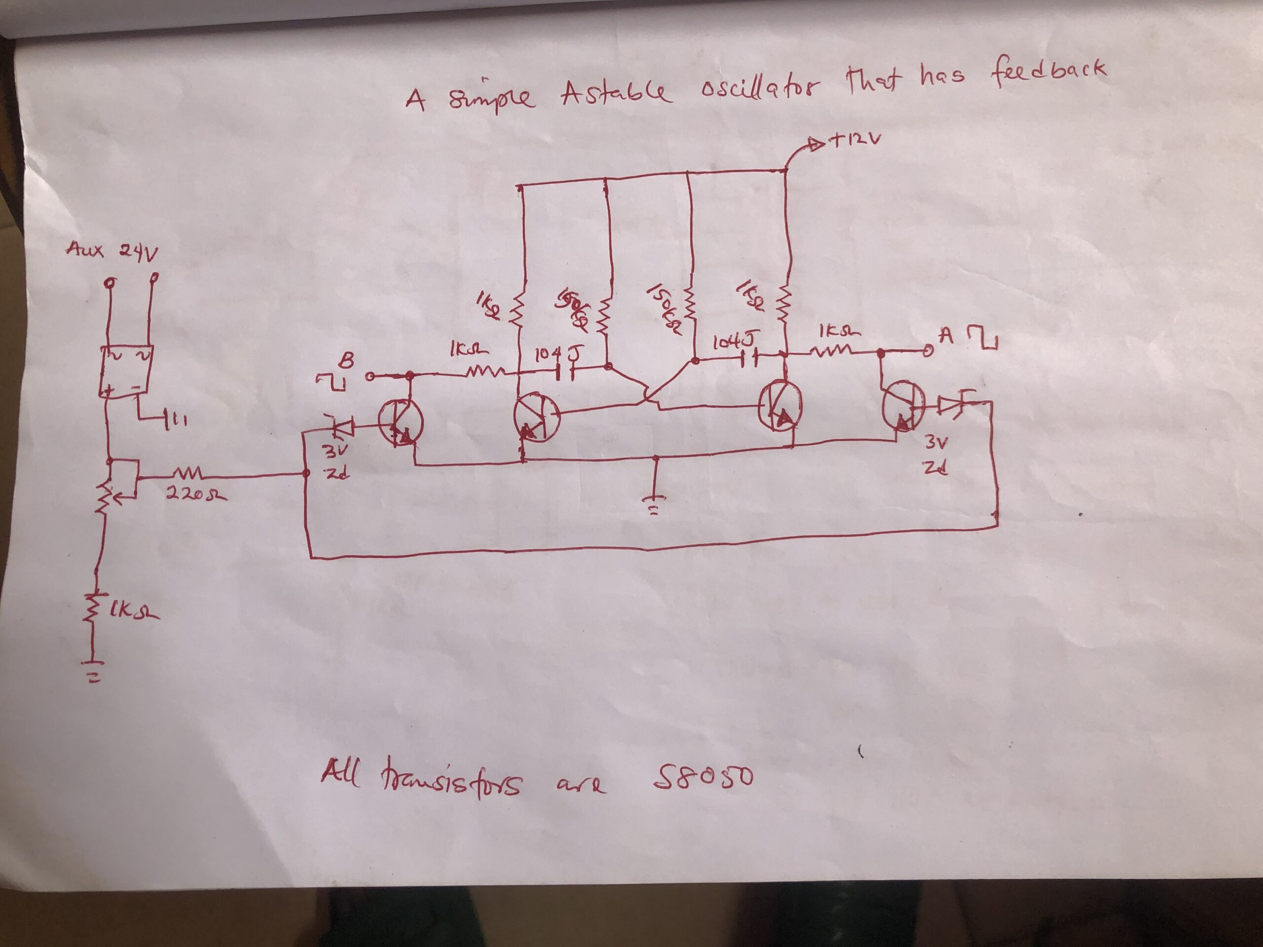
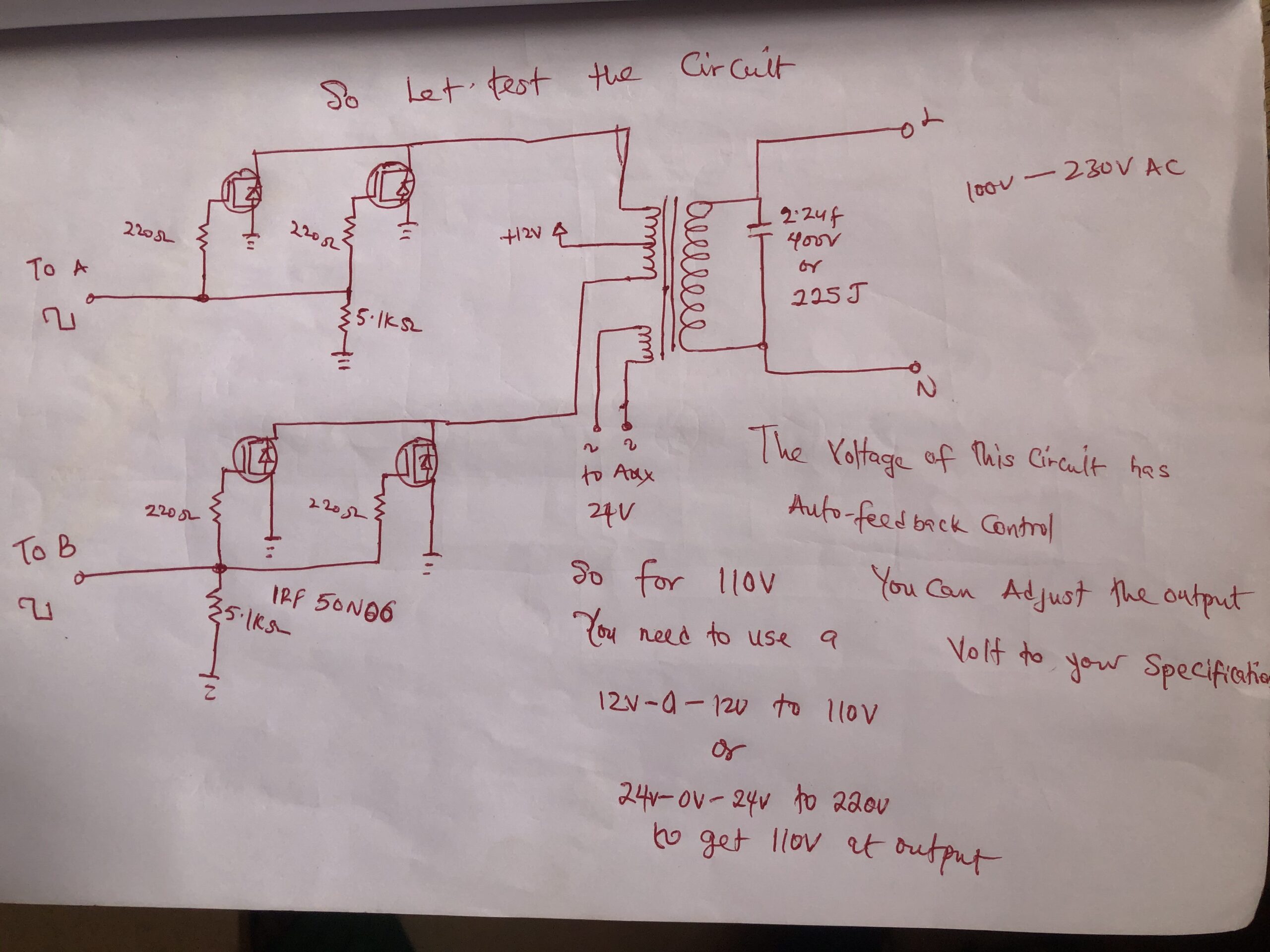
Hey today I am sharing a simple inverter project that has output voltage feedback control and it doesn’t use any ic (integrated circuit), I will explain how it works in this post.
About the inverter project
I will explain how an astable inverter works, so firstly below is an explanation of an astable oscillator.
An astable oscillator is a kind of electronic circuit that creates a consistent series of heartbeats without the requirement for any outer information. It is otherwise called a free-running multivibrator, and that implies that it has no stable state and continually switches back and forth between two states. These oscillators are utilized in various electronic devices like clocks, timers, and tone generators.
The essential astable oscillator circuit comprises of two enhancing components, like semiconductors or operation amps, associated in a feedback circle with a capacitor and two resistors. The circuit is designed to switch back and forward between two conditions of charging and discharging the capacitor, delivering a square wave yield.
The charging and discharging of the capacitor are constrained by two resistors, R1 and R2, which are associated with a voltage divider design. At the point when the circuit is powered on, the capacitor starts to charge through R1 until it reaches a specific voltage level. Right now, the voltage at the foundation of the principal semiconductor turns out to be sufficiently high to turn it on, which releases the capacitor through the subsequent semiconductor and resistor R2.
As the capacitor releases, the voltage at the foundation of the subsequent semiconductor diminishes, making it switch off. This permits the capacitor to begin charging again through R1, and the cycle rehashes. The time taken for the capacitor to charge and still up in the air by the upsides of R1, R2, and C, and can be calculated utilizing the accompanying formula:
T = 0.69 x (R1 + R2) x C
Where T is the time span of the oscillator, R1 and R2 are the upsides of the resistors, and C is the capacitance of the capacitor.
The frequency of the oscillator can be calculated utilizing the accompanying formula:
f = 1/T
Where f is the frequency of the oscillator, and T is the time span calculated utilizing the formula above.
To change the frequency of the oscillator, the upsides of R1, R2, and C can be changed. Expanding the upsides of R1 as well as R2 or diminishing the worth of C will build the time span and decline the frequency while diminishing the upsides of R1 or potentially R2 or expanding the worth of C will diminish the time span and increment the frequency.
In general, the astable oscillator is a simple and flexible circuit that can be utilized in different electronic devices. Its capacity to produce a consistent series of heartbeats with practically no outer information makes it ideal for applications where an exact and stable clock signal is required.
About this my inverter project
Firstly the inverter oscillator circuit is an Astable multivibrator circuit which means is a square wave inverter but I am able to control the circuit to be able to sense the situation of its output which means you can adjust the output volt to you which to set it to and it has auto feedback which means if you apply to load the output voltage will not drop except if the input power is low or not sufficient to sustain the load so all this function is on it and the circuit components are listed below
Components
- 4 pcs of S8050 transistor
- bridge diode 1pcs
- 3v zener diode
- 104J ceramic capacitor
- 1k resistor 5pcs
- 20k variable or trimmer resistor
- 150k resistor 2pcs
- 220 ohms 5pcs
- 12-0-12 to 220v transformer which has auxiliary winding
- IRF50N06 or IRF3205
- 5.1k resistor 2pcs
- 225j or 335j capacitor 1pcs
So below are schematic images drawn by hand


Watch the video of me testing the project
You can download the images an eagle schematic file in the link below
>>>Click here to download the project<<<
