Today I’m sharing a project I’m dealing with which is the pic12f683 unadulterated sine wave inverter project
- Present the idea of a Pic12f683 unadulterated sine wave inverter.
This Pic12f683 sine wave inverter project is a non-complex inverter project that delivers an unadulterated sinewave of 50hertz at the result which just purposes two ic’s (Coordinated circuits) and here, I will share both the schematic and the hex code and, surprisingly, all the project records not barring the board brd picture for the people who do custom made Do-It-Yourself PCB - Benefits of utilizing this Pic12f683 sine wave inverter.
The upside of utilizing this pic12f683 sine wave inverter is that it is entirely adaptable and simple, and that implies it has straightforward circuitry, only 2 ICs each having 8 pins. - Benefits of utilizing this sine wave project
this project is a generally excellent inverter project for hardware understudy who maintains that should do their college last year project, the project is extremely modest, and a financial plan well disposed of, of, and easy to see so anybody with fundamental electronic information will actually want to grasp it. - Look into the upsides of utilizing this pic12f683 sine wave inverter circuit versus other sine wave inverters circuit
- It is modest to fabricate which mean is financial plan is cordial for gadgets understudies
- The circuit is straightforward and comprises just 2 coordinated circuits (Ic) and a few semiconductors including MOSFETs
- The project is a free open-source project which implies anybody could download and involve it for their gadget’s practicals
ABOUT THIS PROJECT
this project was first made by Hung Pham and me and a large portion of its supporters are keen on the project, yet the project has a few issues, most believe is the product yet it is a major NO, the product is unblemished The issue is the equipment, I saw that the issue is from the MOSFET driver (IR2103) whenever you associate the 12v stock to it, The high side result of the MOSFET driver is bringing out 12v rather than 6v and the reason for this is that the MCU hex record has a 5-sec deferral whenever you on the circuit this will cause the ir2103 high side to on however the low side will off and this will set off the MOSFETs with direct voltage which might in fact explode the circuit.
This issue is fixed by adding a defer timer circuit that is preset to 5 seconds and the 5-sec postpone circuit yield is associated with the (VCC) pin1&pin8 of the MOSFET driver and this fixes the issue
defer circuit beneath
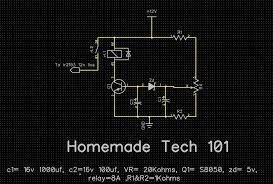
Note: Preset VR to 5sec postponement or something else for the inverter to work
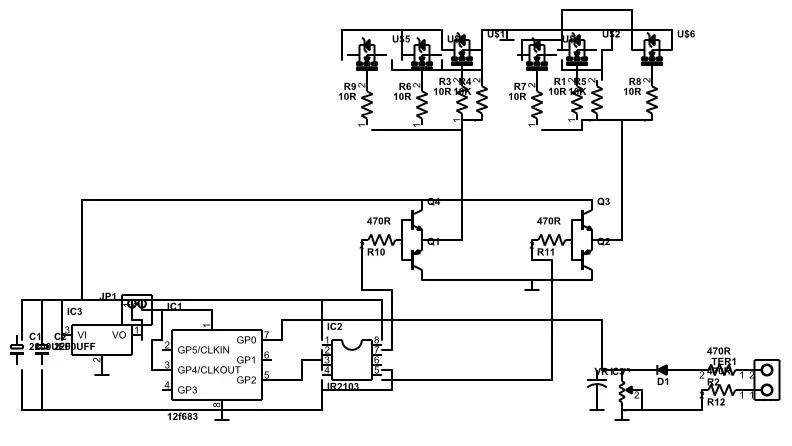
The inverter schematic below
VIDEO BELOW WATCH TO SEE THE INVERTER WORKING
>> Download the mod project file for pic12f683 here<<
follow this blog here to get notified when there is a new post
Can you send me three phase inverter Circuit diagram only 100 wats input 12 or others voltage with code my WhatsApp number+91 9319006269
3 phase pure sine wave inverter project will soon be available, will notify you then