Low Battery Cutoff + Overload/Short Circuit Cutoff + Voltage Feedback Circuit For DIY Inverters
I am sharing a protection circuit for DIY inverters that has 3 functions which are
1. LOW BATTERY CUTOFF:
The low battery cutoff circuit is a circuit that protects the inverter battery from draining (discharging)
led d4 turns on when the battery is lower than the preset voltage which can be adjusted through a 22kohms potentiometer (variable resistor)
How does it work?
2. VOLTAGE FEEDBACK:
The feedback system is a circuit that senses the output level (voltage) of a circuit (inverter).
The feedback circuit in this project is compatible with many DIY oscillators (PWM circuits)
e.g SG3524, TL494, SG3525 etc
which can be preset with the help of a 10Kohms potentiometer (variable resistor) in the VFB section
How does it work?
3. OVERLOAD/SHORTCIRCUIT CUTOFF(CURRENT FEEDBACK CIRCUIT):
The overload/shortcircuit (current feedback) protection prevents circuits from being damaged via overcurrent and shortcircuits In this project the current feedback circuit is a simple one that can be analyzed by anyone with basic electronics.
How does it work?
the shunt resistor is connected in series with the inverter transformer output when a load is connected to the inverter output there will be a voltage drop (build voltage) between the shunt resistor and the voltage between the 2 pins of the shunt resistor is ac low voltage(1v-5v depending on how much load is connected to the inverter, the higher the load the higher the voltage build between the pin of shunt resistor )
w
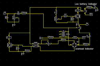
TERMS used in the schematic below:
VFB (voltage feedback)
LIVE (live output of the inverter)
NEUTRAL (neutral output of the inverter)
OSC+ (to inverter oscillator +)